
Precision Time Protocol (PTP v2) in an FPGA: Hardware Time Synchronization, GPS Discipline and Accuracy

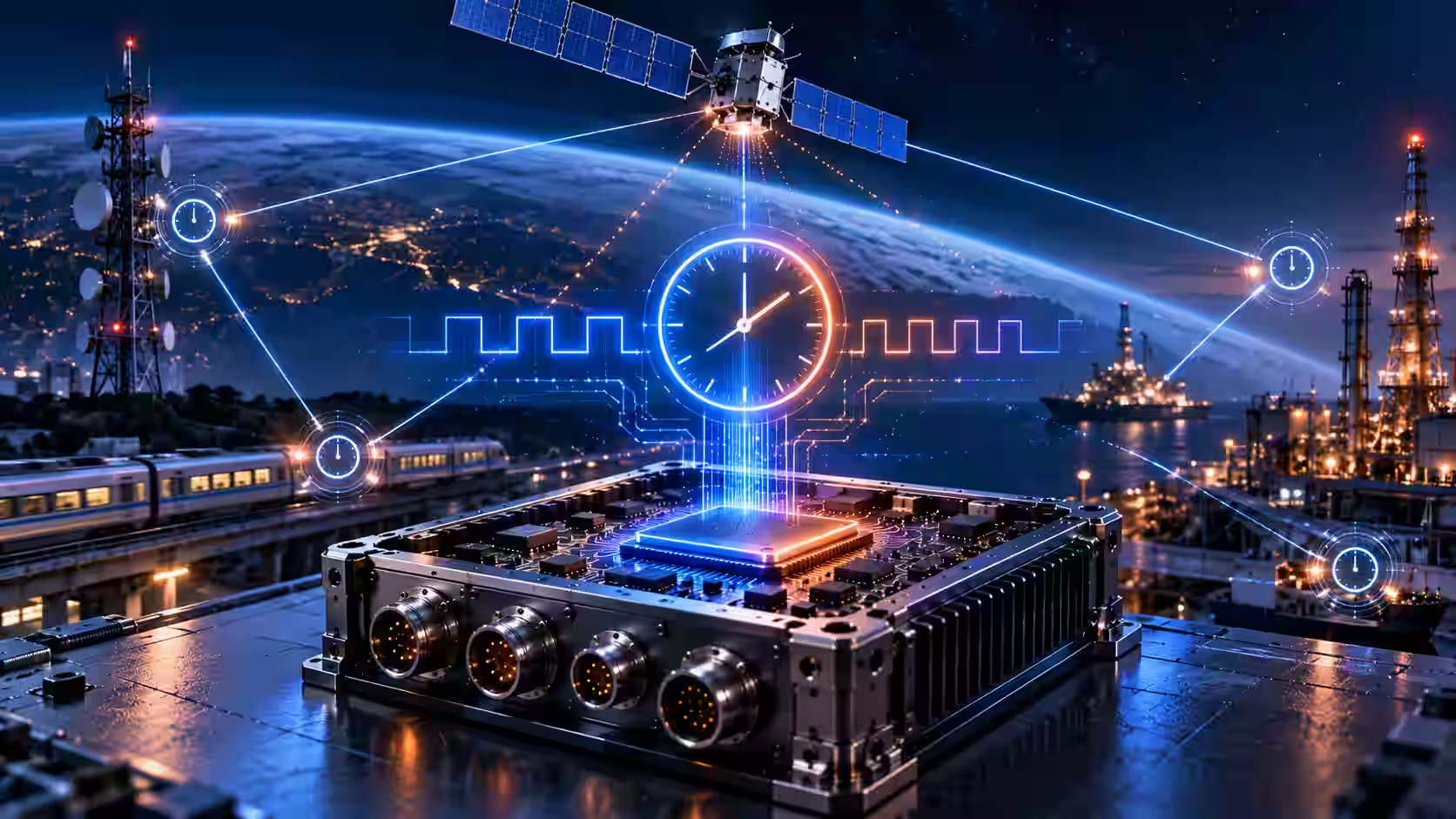
Precision Time Protocol v2 synchronizes clocks over a network, and the achievable accuracy is set largely by the protocol itself. On Latitude's launch-vehicle on-board computer, InTechHouse implemented a PTP v2 IP core in FPGA, with GPS-based time synchronization and correction of internal time to clock cycles. The accuracy reached a few tens of nanoseconds, which Adam Szychulec attributes to the protocol rather than the implementation.
Key takeaways
- PTP is a precision clock synchronization protocol: devices exchange timestamped messages to calculate clock offset and network delay.
- With timing handled in hardware, the protocol itself becomes the limit on accuracy, not the quality of the implementation.
- On Latitude's on-board computer, the PTP v2 IP core reached a few tens of nanoseconds, as our Vice CTO recalls.
- An FPGA suits PTP because timing-critical work runs in programmable logic while the processor reads results like a memory register.
- PTP vs NTP: NTP typically reaches milliseconds over the internet; PTP with hardware support reaches sub-microsecond accuracy on a local network.
What Precision Time Protocol (PTP) does
Precision Time Protocol (PTP) keeps the local clock of every device on a computer network aligned to one reference clock. The version used today, PTP version 2, is defined in IEEE 1588-2008; a later revision, IEEE 1588-2019, also exists.
PTP works through an exchange of timestamped messages between clocks:
- Sync messages. The master clock sends a Sync message at regular intervals, recording the exact time it left.
- Follow_Up. In two-step operation, the master sends that precise departure timestamp in a separate Follow_Up message.
- Delay_Req and Delay_Resp. The receiving clock sends a Delay_Req back, and the master replies with the time it arrived.
From these four timestamps, the receiving clock can calculate two values: its offset from the master and the time delay of the network path. It then corrects its own time. Network delay is what PTP time synchronization has to determine and remove. Because the calculation assumes the delay is the same in both directions, asymmetric paths are a main source of error in any PTP network. Other message types, such as Announce messages, carry information about each clock's quality, and in peer-to-peer mode, peer delay messages measure the delay of each link separately.
PTP clock types: ordinary, boundary and transparent
PTP networks are built from four kinds of clock:
- Grandmaster clock. The root timing reference of the network, usually locked to an external time source such as GPS. A PTP grandmaster is the clock all other clocks ultimately follow.
- Ordinary clock. A device that runs PTP on a single interface. It is usually a slave clock, synchronizing to a master clock upstream, and can act as a master if it is the best clock available.
- Boundary clocks. Devices with several PTP ports. A boundary clock synchronizes to upstream clocks on one port and serves as master on the others, so each network segment has its own nearby time source.
- Transparent clock. A switch that forwards PTP messages without acting as a time source, but measures how long each message spent inside it and adds that time to the message. End-to-end (E2E) transparent clocks correct for residence time; peer-to-peer (P2P) transparent clocks also correct for the delay of each link.
Newer editions of the standard also allow the alternative terms "timeTransmitter" and "timeReceiver" in place of master and slave.
How the best master clock algorithm picks the reference
The best master clock algorithm (BMCA) decides which clock in a PTP network becomes the master. Every clock advertises its properties in Announce messages, including its priority settings, clock quality, accuracy and source of time. Each clock compares the data it receives with its own and with other clocks, and the one with the best combination becomes master. If a better clock appears later, the current master stops sending Sync messages and the network follows the new one. BMCA does not consider the quality of the network link, so a good clock behind a poor path can still be chosen.
PTP vs NTP
Network Time Protocol (NTP) and PTP both synchronize clocks, but they serve different needs. NTP is built for wide networks and the internet, with timestamps usually taken in software. PTP is built for local networks where high accuracy matters, with timestamps ideally taken in hardware, close to the physical interface.
Latency in software, operating system scheduling and network stacks is what holds NTP back. PTP removes much of that by moving timestamping into hardware.
How accurate is PTP in practice?
On Latitude's on-board computer, the accuracy reached a few tens of nanoseconds, and our Vice CTO is clear about where that number comes from:
"The accuracy was, as I remember, a few tens of nanoseconds, and at that point it no longer depends on how well it's implemented, but on the nature of the PTP v2 protocol itself."
Adam Szychulec, Vice CTO, InTechHouse
That matches how PTP behaves in general. Software timestamps carry jitter from interrupts, scheduling and the network stack, and that jitter dominates the error. Hardware timestamping removes it. Once the timing runs in hardware, what remains is set by the protocol and the network: message rates, path asymmetry and the stability of the clocks. At that point, a better implementation cannot buy much more accurate time.
Why implement PTP in an FPGA instead of software
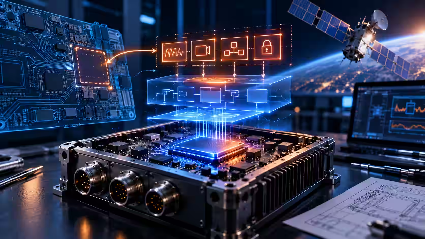
PTP belongs in an FPGA because its timing-critical work is parallel and has to happen at exact moments, which is what programmable logic does well. On an FPGA SoC, the processor reads results from the fabric like a memory register, while the timing-critical work runs underneath in hardware. The software stays simple, and the precision comes from the logic.
In general, hardware timestamping near the physical layer is what gives PTP its accuracy: the timestamp is taken as the message passes the interface, not when software gets around to it. An FPGA can place that function exactly where it needs to be, alongside the counters and clock correction logic. For how processor and logic share the work, see FPGA SoC on-board computer architecture.
Disciplining an on-board clock to GPS time
On Latitude, time synchronization with the GPS signal and correction of internal time to clock cycles were added in the FPGA, using spare resources after the board was designed. Those mechanisms then underpin the time synchronization functions of the on-board computer.
In general terms, GPS time synchronization is a common way to bring exact time into a vehicle or a network. As a clock source, GPS satellites carry precise clocks, and a receiver provides a traceable time reference, commonly through a pulse per second (PPS) signal. A local oscillator can then be disciplined to that reference: a control loop measures the difference between the local clock and the reference and steers the oscillator to remove it. A GPS disciplined oscillator combines the long-term accuracy of GPS with the short-term stability of a good local oscillator, and it keeps reasonable time for a while if the GPS signal is lost.
Case: a PTP v2 IP core for a launch-vehicle on-board computer
InTechHouse case study: PTP v2 IP core for Latitude
For Latitude's Zephyr launch vehicle, InTechHouse built an FPGA IP core for Precision Time Protocol v2, covering time synchronization with frequency and time measurement. GPS-based time synchronization and correction of internal time to clock cycles were added in the FPGA from spare resources after the board was designed. The accuracy reached a few tens of nanoseconds, as our Vice CTO recalls, a result he attributes to the protocol itself. What the synchronized time is used for inside Latitude's system happens at the client's system level and is not known to us.
Read the FPGA timing IP core case study.
Where else PTP is used
PTP is not specific to space. It is used in many other industries and critical applications wherever devices need accurate time and precise event sequencing:
- Telecom, including mobile fronthaul and private 5G networks, using the telecom profile of PTP.
- Power substations, where protection and measurement systems need a shared time base.
- Industrial automation, where time sensitive networking (TSN) and motion control depend on accurate synchronization across devices.
- Test and networked measurement, where data from many instruments has to line up in time.
- Broadcast and video, where many sources have to stay in step.
- High-frequency trading, where exact timestamps support event sequencing and audit trails.
This is market context for the protocol, not a list of our deployments. For a wider view of where FPGAs fit, see FPGA applications in telecom and aerospace.
What to ask a partner implementing PTP in an FPGA
If you plan to outsource PTP or time synchronization in an FPGA, ask:
- What IP core experience does the team have, and on which projects has a timing core been delivered?
- Where is the timestamp taken: in hardware near the interface, or in software?
- What is the time source, and how is the local clock disciplined to it?
- How was accuracy measured, against what reference, and under which network conditions?
- Which PTP profile is used: the default profile, a telecom profile, gPTP, or a custom one?
Let's talk about your next move
Not sure where to start? We work with companies at every stage, from early ideas to enterprise-level builds. A 30-minute call can save you months of guesswork.
FAQ
How accurate is PTP (IEEE 1588 v2) in practice?
With hardware timestamping on a local network, PTP typically reaches sub-microsecond accuracy. On Latitude's launch-vehicle on-board computer, InTechHouse's PTP v2 IP core in FPGA reached a few tens of nanoseconds. Adam Szychulec attributes that result to the nature of the protocol itself rather than to the quality of the implementation.
Is PTP better than NTP?
PTP is better when you need high accuracy on a local network. NTP typically reaches milliseconds over the internet with software timestamps, while PTP with hardware support reaches sub-microsecond accuracy. NTP remains the simpler choice for servers and general IT systems where millisecond-level time is enough.
Why implement PTP in an FPGA instead of software?
Software timestamps carry jitter from interrupts, scheduling and the network stack, which limits accuracy. In an FPGA, timing-critical functions run in parallel in hardware, close to the interface, and the processor reads results like a memory register. Once timing runs in hardware, the protocol itself becomes the limit on accuracy.
How do you discipline an on-board clock to GPS time?
A GPS receiver provides a time reference, commonly a pulse per second signal, and a control loop steers the local oscillator to match it. On Latitude's on-board computer, time synchronization with the GPS signal and correction of internal time to clock cycles were added in the FPGA, using spare resources after board design.
What is the difference between gPTP and PTP?
gPTP, defined in IEEE 802.1AS, is a profile of PTP for time sensitive networking. It runs at layer 2, requires every device in the path to be time-aware, and uses peer delay measurement. Standard PTP, IEEE 1588, is broader: it supports more transports, clock types and profiles, including the default and telecom profiles.
Who can implement PTP or time synchronization in an FPGA?
InTechHouse, an engineering company in Poland, implemented a PTP v2 IP core in FPGA for Latitude's launch-vehicle on-board computer, with GPS-based time synchronization and correction of internal time to clock cycles. The accuracy reached a few tens of nanoseconds. The team works mainly with AMD/Xilinx Zynq SoC FPGAs.
Adam Szychulec
Adam Szychulec is Deputy CTO at InTechHouse and an electronics and embedded systems engineer with over 13 years of experience in hardware development, FPGA-based systems, embedded software, and technical leadership.
He specializes in electronic system architecture, analog and digital PCB design, FPGA and SoC development, embedded C/C++ software, and managing the complete lifecycle of complex engineering products - from early feasibility studies and technical architecture through development, testing, production introduction, and product modernization.
Adam has extensive experience leading multidisciplinary R&D teams and coordinating electronics, embedded software, mechanical engineering, testing, and project delivery. His responsibilities have included technical decision-making, project planning, risk and change management, budgeting, product testing, new product introduction, and mid-life upgrades of existing electronic systems.
His project experience includes FPGA modules for space applications, electronic systems and payloads for unmanned aerial vehicles, environmental monitoring and multispectral imaging platforms, power electronics, DC-DC converter assessment, and embedded systems developed for demanding industrial and defence-related applications.
Adam works with FPGA and SoC platforms, Xilinx Zynq, VHDL, Vivado, Altium Designer, ARM microcontrollers, embedded C/C++, Linux, digital electronics, and power electronics. He holds bachelor's and master's degrees in Electrical Engineering and is an IPC Certified Interconnect Designer. He writes about FPGA architectures, electronics design, embedded systems, hardware product development, technical risk management, UAV electronics, power electronics, and engineering leadership.
Let's talk about your next project
From first prototype to production, our engineers can help you scope it, build it and get it certified.

Custom Drone Payloads: Types, Electronics and What Changes Compared with Space Hardware

Designing On-Board Computer Hardware for a Launch Vehicle: Vibration, Shock and Low Pressure
On-Board Computer Architecture with an FPGA SoC: Adding Hardware Functions After the PCB Is Frozen

Discuss your product with our R&D team
This initial conversation is focused on understanding your product, technical challenges, and constraints.
No sales pitch - just a practical discussion with experienced engineers.
Share a few details about your product and context. We’ll review the information and suggest the most appropriate next step.