


Custom On-Board Computer Development for Launch Vehicles, UAV and Defence
InTechHouse designs custom on-board computer hardware for launch vehicles, UAV programmes and defence: the electronics, FPGA IP cores, an enclosure designed for testing and vibration, and the path through EMC and environmental qualification.


Proof: a fully qualified on-board computer for a launch vehicle
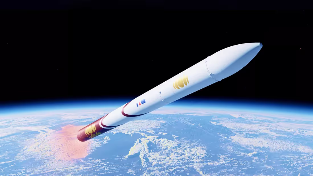
We designed the on-board computer for Latitude’s Zephyr launch vehicle as one system: electronics, FPGA logic and enclosure. We ran EMC pre-compliance in our own lab, then managed the formal EMC and environmental tests in accredited laboratories. Latitude received the full report set, the documentation and the IP.
Turn your mission requirements into qualified on-board hardware
Discuss your interfaces, environment and test regime with engineers who have taken an on-board computer through EMC and environmental qualification for a launch vehicle. We cover the board, FPGA logic and enclosure as one system.

What our on-board computer development covers
One team designs the board, the FPGA logic and the enclosure, then takes the unit through qualification. We delivered every item below on the Latitude on-board computer.
Hardware, FPGA and enclosure design
- Schematics and PCB layout built around your interfaces and power budget
- FPGA logic and FPGA IP cores for time and frequency synchronization
- Enclosure designed together with the PCB for testing and vibration
- Design suggestions for the wiring harness that connects the unit to the vehicle
Qualification and handover
- EMC pre-compliance measured in our own lab
- Formal EMC and environmental tests in accredited laboratories, under our responsibility
- Complete report set for your declaration of conformity
- Design documentation and IP transferred to your team
Hardware, FPGA and qualification under one team
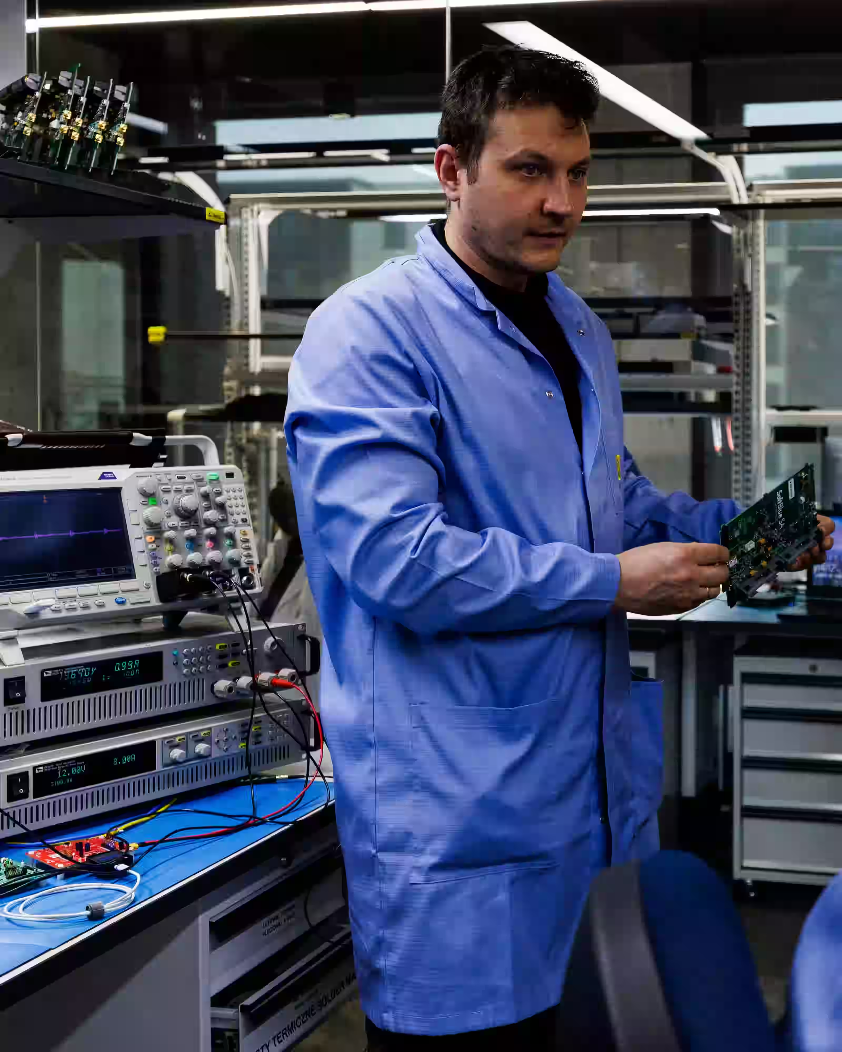
We cover the three disciplines an on-board computer depends on: the board and enclosure, the FPGA SoC architecture and the qualification campaign. One team owns all three, so interface and test problems get solved inside the project.

Hardware and Enclosure Design
We design the schematics, PCB layout and enclosure as one system. Power is built around PMICs, and the mechanical design targets vibration, shock and conduction cooling in vacuum.

FPGA SoC Architecture and IP Cores
A processor runs the base software, and programmable logic takes parallel, timing-critical work and any missing interfaces. Spare FPGA resources leave room to add functions after the board is frozen.

EMC and Environmental Qualification
We design for EMC from the schematic stage and run pre-compliance in our own lab. We then manage the formal EMC and environmental tests in accredited laboratories, under our responsibility.
“We've worked for almost three years with InTechHouse and it became a successful partnership along the years with the delivery of a fully qualified On-Board Computer for space vehicle.
It started with software and hardware development, then casing and PCB routing and finally an environmental qualification. Some steps were harder than others like any electronics project but the team was always available, efficient and professional. The success of this first journey allow us to think about our future avionics developments with InTechHouse.”


What stays with your team: flight software and the IP
We deliver the hardware platform, the FPGA logic and the qualification path. Your team owns the flight software and flight control, and at project close the design files, documentation and IP transfer to you. On the Latitude program, Latitude’s engineers wrote the flight software.
What we deliver
- Hardware platform: schematics, PCB layout and enclosure
- FPGA logic and FPGA IP cores
- Qualification path through EMC and environmental testing
- Board, FPGA and enclosure integrated by one team
What stays with your team
- Flight software and flight control
- Design files and full documentation, transferred at project close
- Intellectual property of the design
- Your choice of who manufactures the unit and who changes it next
Custom single-board computer or off-the-shelf?
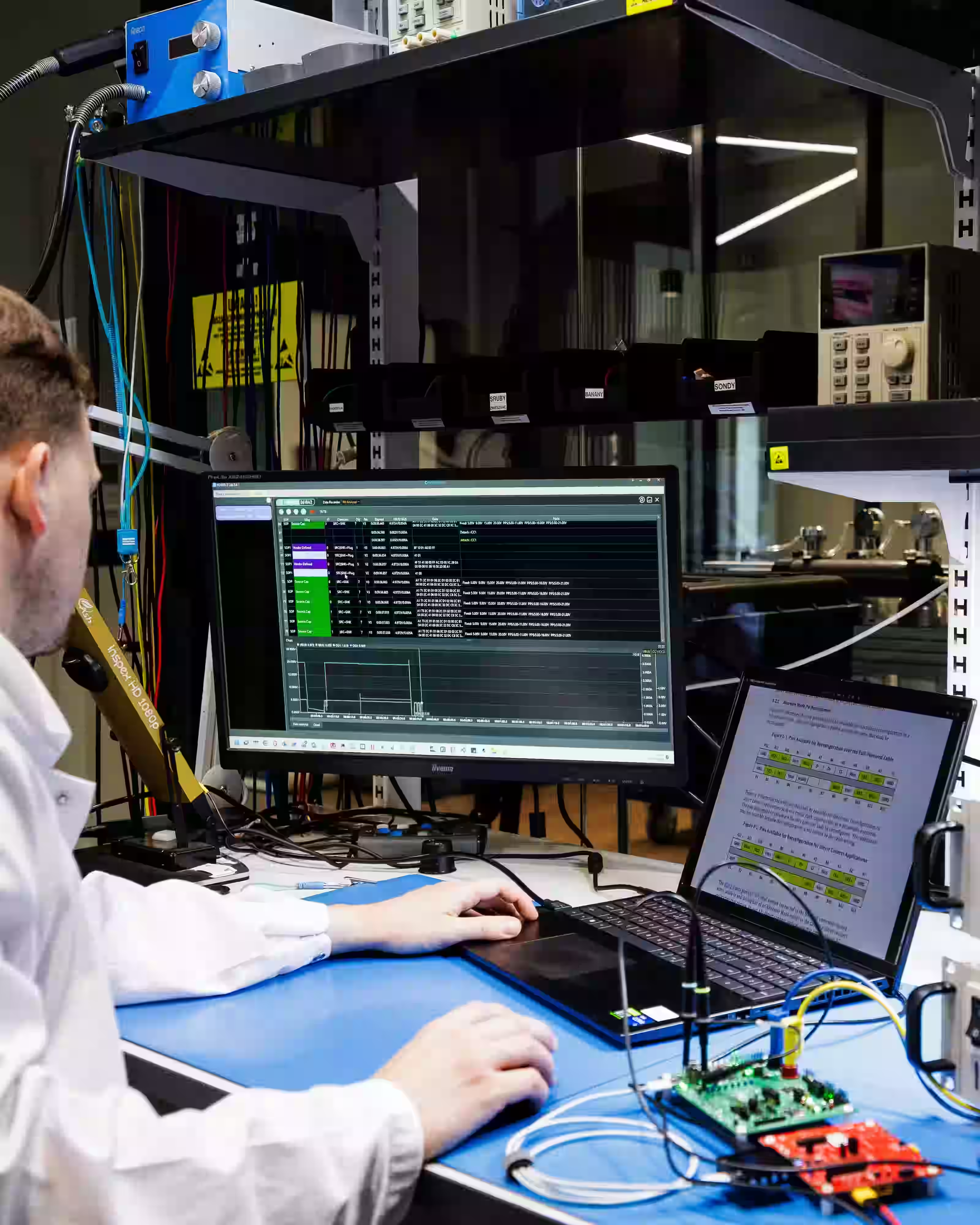
A custom single-board computer makes sense when no standard SBC meets your interfaces, environment or IP requirements. When an off-the-shelf board covers the mission, we recommend buying it and designing the system around it. The choice usually comes down to three options, and we work with all of them.
Qualification: EMC first, then environmental
The Latitude on-board computer went through a customer-specified test regime: EMC to MIL-STD-461G and environmental testing to MIL-STD-810, both tailored with ECSS-derived requirements. We run EMC first because an EMC failure usually means a hardware change, and environmental results collected on the old revision would have to be repeated. That is why EMC is part of the design from the schematic stage, before any test starts.
What typically goes wrong, and how we design against it
Launch exposes an on-board computer to vibration, shock, falling pressure and vacuum within minutes. Most qualification failures come from a handful of known risks, so we design against each one before the first test. Low pressure is treated as its own design case, with separate checks, because electronics that pass at ground level can behave differently during ascent.
Resonance under vibration
When a PCB or enclosure resonates, it multiplies the load the vehicle puts into it. We design the board and the enclosure for stiffness, so their resonances stay clear of the vibration profile.
Parts outside the temperature range
A single component rated below the declared temperature range can fail the whole unit. We check every part against the range at schematic stage, before the board goes to layout.
Heat with no path out in vacuum
Without air, convection stops working, and a heat source with no conduction path overheats. We connect every significant heat source to the enclosure through heatsinks or thermal pads.
Late EMC failure
An EMC failure found late usually means a hardware change, and environmental results from the old revision have to be repeated. We design for EMC from the first schematic and run pre-compliance in our own lab.
Three suppliers, three interfaces
When the board, FPGA and enclosure come from separate subcontractors, problems collect at the interfaces between them. One team designs and integrates all three, so those problems get solved inside the project.
UAV payloads and ground control stations
We have worked on UAV programs for Polish Armaments Group (PGZ) for five years or more. Our scope covers the mission payloads and the ground control station; the flight controller stays outside it. Each payload combines sensors, onboard processing and data links in a unit sized for the airframe and built for field conditions.
How an engagement runs
An on-board computer project moves through five stages, and each one produces the input the next one needs. We work on a time and material basis, so the scope can adjust to what prototypes and tests reveal.
Step 1: Requirements and interfaces
We define what the on-board computer connects to, the environment it has to survive and the standards it has to pass. The test regime is fixed at this stage, so the design is built against it.
Step 2: Architecture decision
We choose between a COTS single-board computer, a system-on-module on a custom carrier board and a fully custom design. We also choose between a processor and an FPGA SoC. The choice follows your interfaces, environment and IP needs.
Step 3: Hardware, FPGA and enclosure design
One team designs the schematics, PCB layout, FPGA logic and enclosure together. EMC, stiffness against resonance and conduction cooling are part of the design from the first schematic.
Step 4: Prototypes and qualification
We build prototypes and run EMC pre-compliance in our own lab. Formal EMC and environmental tests then run in accredited laboratories under our responsibility.
Step 5: Handover and production support
You receive the design files, documentation and IP. We support the move into production, and spare FPGA resources leave room to add functions later.
Selected case studies




FAQs
If you have additional questions or would like to discuss your requirements, feel free to get in touch with our team.
InTechHouse covers the on-board computer hardware: schematics, PCB layout, FPGA logic and FPGA IP cores, an enclosure designed for vibration and shock, and wiring harness design suggestions. The team also runs in-house EMC pre-compliance, manages formal EMC and environmental tests in accredited laboratories, and transfers the documentation and IP to the client.
No. InTechHouse delivers the hardware platform, FPGA logic and qualification path, and the client's team owns the flight software and flight control. On the Latitude on-board computer, Latitude's engineers wrote the flight software. This split lets launch vehicle teams keep mission logic in-house while one supplier handles board, FPGA and enclosure.
The on-board computer InTechHouse delivered for Latitude went through a customer-specified test regime: EMC to MIL-STD-461G and environmental testing to MIL-STD-810, both tailored with ECSS-derived requirements. Formal tests ran in accredited laboratories under InTechHouse's responsibility, after in-house pre-compliance, and produced the report set for the client's declaration of conformity.
Yes. If a standard single-board computer covers the required computing power, interfaces and environmental conditions, InTechHouse recommends using it and designs the system around it. A system-on-module on a custom carrier board is a middle option. A fully custom design makes sense when the interfaces do not exist off the shelf or the client needs to own the IP.
The client does. At the end of an on-board computer project, InTechHouse transfers the design files, test reports and full documentation, together with the intellectual property. The client can then manufacture the unit, modify the design or bring in another supplier, without depending on InTechHouse for future changes.
Yes, when the architecture leaves room for them. With an FPGA SoC, spare programmable logic can take new functions after the board is frozen. On the Latitude on-board computer, spare FPGA resources were later used to add GPS time synchronization and correction of internal time to clock cycles, through a PTP v2 IP core.
Yes. For Polish Armaments Group (PGZ), InTechHouse has worked on UAV programs for five years or more, building air sampling, real-time air analysis, water sampling and multispectral imaging payloads, plus a rugged IP66 ground control station. The multispectral payload is built on a Zynq-7000 SoC. InTechHouse does not build UAV flight controllers.
With a technical conversation about requirements and interfaces: what the on-board computer must connect to, the environment it must survive and the standards it must pass. InTechHouse then recommends an architecture (COTS, system-on-module or custom; processor or FPGA SoC) and moves into design. Projects run on a time and material basis.
Discuss your on-board computer project with our engineering team
This first conversation focuses on your vehicle, its interfaces and the qualification you need to pass. No sales pitch, just a practical discussion with the engineers who would work on your project.


Share a few details about your product and context. We’ll review the information and suggest the most appropriate next step.