A collision avoidance system is an onboard safety technology that detects hazards ahead of a moving vehicle and intervenes, either by warning the driver or by applying the brakes automatically, before a collision occurs. On a tram or light rail vehicle, that definition carries a constraint that changes everything: the vehicle runs on a fixed track and cannot steer around an obstacle. If something is in the way, the only option is to stop in time. This page covers how AI-powered collision avoidance works on rail, why the problem is fundamentally different from automotive ADAS, and what a deployable ADAS rail system looks like in practice..
Key Takeaways
The automotive ADAS baseline is well established. UN-ECE Regulation 131 requires a system that can automatically detect a potential forward collision and activate the vehicle braking system to decelerate the vehicle with the purpose of avoiding or mitigating a collision. UN-ECE Regulation 152 specifies a minimum deceleration of 5 m/s². Euro NCAP has assessed AEB systems for city, interurban, pedestrian, and cyclist scenarios since 2014. The automotive industry's goal is the same as rail's: prevent accidents entirely, reduce near-misses, and cut injury severity in unavoidable impacts.
The fundamental assumption in automotive ADAS, however, is that steering remains an option. A car approaching an obstacle at speed can brake and swerve simultaneously. At highway speeds, a lateral maneuver of 2–3 meters takes the vehicle clear of most obstacles. That escape route does not exist on a tram. The track dictates the path. The tram will hit whatever is on the rails unless it stops before reaching it.
That constraint makes three things worse for rail than for road. First, stopping distances are longer: a modern low-floor tram weighing 30–40 tonnes travelling at 50 km/h needs 40–60 meters to stop under full emergency braking on a dry rail (Knorr-Bremse, 2024), compared to 14–20 meters for a car at the same speed. Wet or leaf-contaminated rail extends that distance further. At low speeds, below 30 km/h, the risk of fatality drops sharply with each meter of stopping distance gained. At 50 km/h, a tram that stops 10 meters earlier than it otherwise would have is the difference between a near-miss and a fatal collision. Second, trams operate in shared urban space: pedestrians crossing on green, cyclists cutting across stops, and road vehicles blocking tracks at intersections are all routine hazards, not edge cases. Third, the detection system must fire early enough for the braking distance to be covered, which means classifying a hazard correctly at 30–50 meters while the vehicle is moving, often in poor lighting or rain.
Obstacle detection systems can improve both train punctuality and safety. In the future, the obstacle detection system can help drivers avoid accidents, which will stabilize daily S-Bahn operations and increase punctuality. The system promises to be a key technology for enabling digitalized, fully automated rail operations. The direction of travel is clear: Siemens Mobility has embarked on a project to test an obstacle detection system on the Berlin S-Bahn as part of the Digital Rail Germany (DSD) initiative. This marks the first-ever installation of such a system on S-Bahn trains in daily operation, specifically on the latest 484 series.
The pipeline has four stages, each of which must complete within the vehicle's time budget before the stopping window closes.
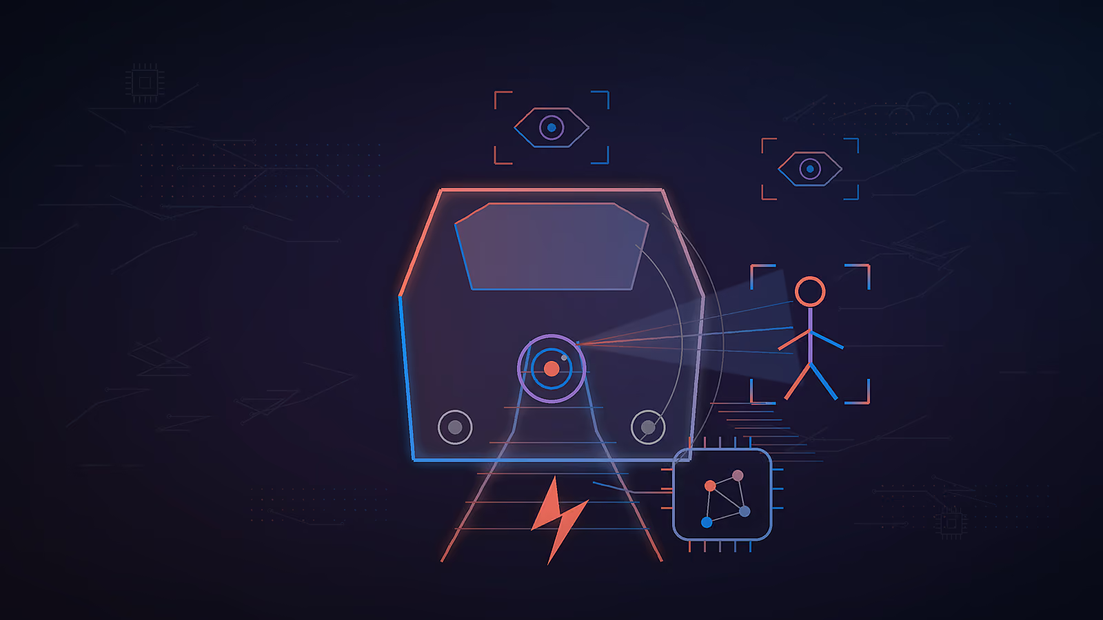
Front-facing cameras and LiDAR units continuously scan the track ahead. The camera provides a high-resolution image stream for classification. The LiDAR provides a point cloud that gives precise distance, size, and position data for any object in the field of view. Together they cover the detection range needed to initiate braking at operating speed. The sensors used in the Siemens Berlin S-Bahn project include high-performance LiDARs for close- and long-range object detection and an infrared camera.
The AI model applies detection algorithms to camera frames and fused sensor data in real time, detecting and classifying objects: pedestrian, vehicle, static obstacle, track infrastructure. The model must distinguish between a hazard that requires braking and the dense, variable background of an urban street: road markings, parked vehicles, cyclists on adjacent lanes, platform furniture. The algorithms for evaluating the sensor data have been specially developed for the rail sector in the "Berlin Digital Rail Operations - BerDiBa" research project by Siemens in Berlin-Adlershof and have already been optimised several times. Generic automotive detection models do not transfer to rail environments without substantial retraining on domain-specific data.
The system calculates whether the detected object intersects the vehicle's path and whether the current speed and deceleration capability allow a stop before impact. This calculation requires knowing the vehicle's current speed, the estimated stopping distance (which varies with rail condition, gradient, and vehicle load), and the distance to the obstacle. The system continually compares the position of a train with the location of detected objects using a digital map, and makes decisions on whether to warn the driver or brake.
If the risk assessment confirms a collision is probable without action, the system either issues a driver alert (for a hazard within the warning zone but outside the emergency zone) or sends a brake command directly to the vehicle controller. That command travels over a hardware interface (typically UDP, CAN bus, or a proprietary brake control protocol) to the vehicle's braking system, which applies partial or full emergency braking depending on the severity threshold. This is what practitioners mean by automatic braking AI: not a single model, but a full pipeline from sensing to actuation.
All four stages run onboard, on embedded hardware, without any cloud call. For detailed sensor architecture, see sensor fusion at the edge. For hardware selection, see edge AI hardware for in-vehicle systems.
A front-facing mono camera handles object detection and classification, typically running at 1080p and 30–60 FPS with a 60–90° horizontal field of view.
A front-facing stereo camera pair enables depth estimation and obstacle sizing, requiring matched focal length and hardware synchronization between the two cameras.
Long-range LiDAR provides distance measurement and point-cloud generation, typically covering a range of 100–200 meters with 0.1° angular resolution.
Short-range LiDAR handles close-obstacle and platform detection, typically covering a range of 20–50 meters with a wide field of view.
Infrared/thermal cameras support night and adverse-weather detection, typically operating at 320x240 or 640x480 resolution in the LWIR band.
Radar, positioned as a future-ready sensor, provides all-weather velocity and range measurement, typically using 77 GHz FMCW radar with a range of 150+ meters.
The camera provides the rich image data needed for classification. LiDAR provides metric precision for distance and obstacle geometry that camera-only systems cannot match reliably at range. The combination of both in a sensor fusion architecture improves performance across the full range of operating conditions: day, night, rain, fog, glare from oncoming headlights, and direct sunlight on wet rails.
Radar systems are worth designing in as a future-ready addition even if not activated in the initial deployment. It adds all-weather velocity measurement and operates through precipitation that attenuates LiDAR returns, making it the natural redundancy layer for weather-degraded scenarios. See sensor fusion at the edge for fusion architecture details.
Mounting and retrofit. On new rolling stock, sensor positions can be designed into the front cab structure with appropriate cable routing and weatherproofing. On retrofit deployments, sensors must be mounted on existing exterior surfaces with through-hull cabling to the onboard compute unit. Mounting alignment is critical: a camera tilted 2 degrees from the intended axis shifts the detection zone at 30 meters by over a meter, which can cause missed detections or false positives at track edges. Calibration after installation is not optional.
Environmental robustness requirements
Fog reduces LiDAR range and causes contrast loss in camera images; this can be mitigated with a thermal camera and radar as backup sensors.
Rain introduces noise into LiDAR readings and causes water droplets to accumulate on camera lenses; heated lens housings and sensor fusion help address this.
At night, cameras lose contrast and color information; relying primarily on IR/thermal cameras and LiDAR helps compensate.
Direct sunlight can saturate camera sensors; using an HDR camera and treating LiDAR as the primary sensor mitigates this issue.
Snow on the lens can cause total sensor blockage; heated housings combined with automatic fault detection help prevent and identify this failure mode.
Electrical interfaces must be matched to the vehicle's auxiliary power supply (typically 24V or 110V DC on European trams). Communications interfaces between sensors and the compute unit use standard protocols (USB 3.0, GigE Vision for cameras; Ethernet or serial for LiDAR) but must be implemented with automotive or industrial-grade connectors rated for the vehicle's vibration and temperature profile. Position data from a GNSS receiver, combined with a digital map, improves risk assessment accuracy by providing track geometry context (curves, gradients, known crossing positions) that sensor data alone cannot supply. Systems capable of combining GNSS position with centimetre-level digital mapping can pre-flag known hazard zones (level crossings, pedestrian hotspots) before the sensors even detect an object.
The detection pipeline processes each camera frame through a deep learning object detection model (typically a variant of YOLO, EfficientDet, or a custom architecture optimized for rail domain data) that classifies detected objects into categories: person, animal, vehicle, static obstacle, track infrastructure (signals, buffers, other trams).
Detection accuracy depends entirely on training data quality and domain coverage. A model trained on automotive datasets will perform poorly in a tram environment: rail track geometry, low platform heights, and urban crossing scenarios are structurally different from road scenes. The training dataset must include examples from the actual operating environment across seasons, lighting conditions, and weather states.
Anomaly detection handles the harder problem: objects the model was not trained on. A suitcase left on the track, a fallen tree branch, construction debris. None of these will appear frequently enough in training data to be learned as explicit classes. An anomaly detection strategy runs in parallel with the object classifier, flagging any detection that does not match known background patterns, even if it cannot be classified. That flag routes to the driver alert rather than automatic braking, preserving human judgment for unknown objects. See video anomaly detection for safety.
Small object detection is the hardest case. A person lying on the track at 40 meters, viewed through a rain-covered lens from a moving vehicle, may occupy fewer than 50 pixels in the image. Standard detection models fail on objects this small. Tiling approaches (SAHI: Slicing Aided Hyper Inference) improve small-object recall by running the model on overlapping crops of each frame, detecting small objects within each crop, then merging results. See small object detection with SAHI.
The target true positive rate for detecting a pedestrian at 30 meters is above 97%, while the target true positive rate for detecting a static obstacle at 50 meters is above 95%. The false positive rate should stay below 0.5 events per kilometer operated, and detection latency from sensor input to classification should remain under 30 milliseconds. The minimum detection range is speed-dependent and detailed further in the braking distance table.
Braking integration requires precise definition of the intervention thresholds and a hardware interface that the vehicle's braking system will accept.
Intervention zones. The system operates with two concentric zones ahead of the vehicle. The outer zone (warning zone) triggers a driver alert when an obstacle is detected. The inner zone (emergency zone) triggers automatic braking so the system can react quickly if the obstacle has not been cleared and the driver has not intervened. Zone boundaries are calculated dynamically from current vehicle speed, the estimated stopping distance for current rail conditions, and a reaction time margin.
Stopping distance at operating speeds
At 20 km/h, stopping distance ranges from 10–15 meters on dry rail and 15–25 meters on wet rail. At 40 km/h, it increases to 30–45 meters on dry rail and 50–70 meters on wet rail. At 50 km/h, stopping distance ranges from 45–65 meters on dry rail and 70–100 meters on wet rail. At 70 km/h, it reaches 80–120 meters on dry rail and 120–180 meters on wet rail.
Figures are indicative for a 30–40 tonne low-floor tram under full emergency braking. Actual values depend on vehicle mass, brake system design, gradient, and rail condition (Knorr-Bremse, 2024; rail deceleration values typically 0.8–1.3 m/s² service braking, 1.3–2.5 m/s² emergency braking, compared to automotive emergency braking at 5–10 m/s²).
Braking interface. The brake command is sent from the AI compute unit to the vehicle controller over a hardware interface. Common options include a relay or dry-contact output wired into the emergency brake circuit (simplest, least integrated), a CAN bus message to the vehicle control unit (tighter integration, requires vehicle documentation), or a UDP message over an onboard Ethernet network to a dedicated brake controller. The interface choice depends on what the vehicle OEM permits and what the safety case requires. For automatic braking functions that bypass the driver, the interface must be validated as part of the functional safety documentation.
Low-speed graceful stop. At low speeds (under 15 km/h, typically in depot or platform zones), the system applies partial braking rather than full emergency braking, bringing the vehicle to a smooth stop. Full emergency braking at low speed is unnecessarily harsh for passengers and may cause falls in the cabin. The speed threshold for switching between graceful stop and emergency stop behavior is configurable.
The decision making hierarchy defines which conditions trigger which interventions, and in what order:
Alerts use visual (display with obstacle location and type), audio tones (distinct sound for warning vs. emergency), and optionally haptic (seat vibration) modalities. The combination ensures the driver receives the alert regardless of cab noise levels or attention state.
Operator override. The driver must be able to override or cancel the automatic braking command at any time. The system does not lock the driver out. If the driver cancels an automatic brake application, the system logs the event and continues monitoring. Persistent override behavior (a driver who cancels alerts repeatedly over a shift) is flagged in the operational telemetry for supervisor review.
Explainability. The operator needs to understand why the system braked. A system that produces unexplained stops erodes trust faster than any false positive. The onboard display should show the detected object type, its position relative to the vehicle, and the confidence score. The goal is to assist the driver in understanding the decision immediately, not to replace their judgment. See explainable AI for safety alerts.
Lab validation uses recorded sensor datasets replayed through the detection pipeline to measure detection rates and latency without requiring a vehicle. Datasets should cover each environmental condition independently (night, fog, rain, glare) and include adversarial cases (partial occlusion, small objects, clutter at track edges).
Field testing must cover all seasons and operating conditions that the deployed system will encounter. A one-year test cycle is the practical minimum for a system deployed in a continental climate: summer glare, autumn leaves on rails, winter darkness and ice, spring rain. The test phase for the Siemens Berlin S-Bahn system will run for a year, to cover all seasons, with the data to be used to refine the system and optimise the positioning of the sensors.
Scenario coverage for field tests
For a pedestrian crossing at 30 meters in dry, daylight conditions, the key metrics are detection rate and false positive rate. For a static obstacle at 50 meters on wet rail at dusk, the key metrics are detection rate and stopping distance. For a moving vehicle entering the track at a junction, the key metrics are classification accuracy and reaction time. For night operation with oncoming headlights, the key metric is detection rate under glare conditions. For fog with visibility under 50 meters, the key metric is detection range degradation. For a crowded urban crossing with multiple moving objects, the key metrics are false positive rate and system latency.
Third-party validation. For systems with automatic braking functions, independent validation by a notified body or accredited test laboratory is required. The test plan must be agreed in advance, documented, and the evidence retained for the safety case file. After each test phase, evaluate results against pre-defined thresholds before signing off on deployment.
Rail safety-critical systems in Europe operate within the CENELEC framework: EN 50126 (RAMS requirements), EN 50128 (software for railway control), and EN 50129 (safety-related electronic systems). The applicable Safety Integrity Level (SIL) depends on the function: a driver advisory alert carries lower SIL requirements than an automatic braking function that bypasses the driver. Compliance evidence includes hazard analysis and risk assessment, failure mode effects and diagnostic analysis (FMEDA), software development lifecycle documentation, and independent safety assessment. Teams that develop safety cases in parallel with the product, rather than retrospectively, compress the certification timeline significantly. Experience with these standards is a practical filter when choosing an edge AI development company, since safety cases are hard to retrofit onto an existing product.
The automotive baseline provides useful context for buyers and procurement teams who know those frameworks better than CENELEC. UN-ECE Regulation 131 requires a system that can automatically detect a potential forward collision and activate the vehicle braking system to decelerate a vehicle with the purpose of avoiding or mitigating a collision. UN-ECE Regulation 152 specifies a minimum deceleration of 5 m/s². NHTSA projected that the accelerated rollout of AEB would prevent an estimated 28,000 collisions and 12,000 injuries annually in the US market. Euro NCAP has assessed AEB systems for pedestrian and cyclist scenarios since 2018. Rail systems are not subject to these automotive regulations, but the performance targets they encode (detection range, deceleration thresholds, pedestrian classification) are useful benchmarks for specifying rail system requirements.
IEC 62280 covers cybersecurity requirements for railway communication systems and is relevant to any onboard system with a network interface for OTA updates or telemetry transmission. A vendor with deep knowledge of both CENELEC rail standards and the automotive AEB baseline can map the requirements gap and build a compliance plan that satisfies both audiences. Verify current applicable standards with the relevant national safety authority before finalizing.
OEM integration. New rolling stock can be equipped with the collision avoidance system from the factory, with sensor positions, cable routing, and power allocation designed in from the start. Sensor positions, cable routing, power supply allocation, and controller interface are specified in the vehicle design package. The system supplier works alongside the OEM during design freeze, with integration testing on the first-off vehicle before series production.
Retrofit. Retrofitting onto an existing fleet is feasible but more complex. Sensor mounting requires external brackets (with weatherproofing and vibration isolation), cabling must be routed through existing conduits or new surface-mounted trunking, and the brake interface must be agreed with the vehicle maintainer and documented in the vehicle modification record. Retrofit projects should plan for a full calibration run after installation on each vehicle. Development of a vehicle-specific calibration protocol before the first installation saves time across the fleet.
Maintenance and calibration schedule
Sensor cleaning, covering the lens and LiDAR window, should be performed weekly or after adverse weather. Alignment and calibration checks should be carried out every 3 months or after a collision or impact. Model performance review, based on the false positive rate, should be conducted monthly using operational telemetry. Firmware and model updates should occur quarterly, or sooner if performance degradation is identified. A full system functional test should be performed annually.
Calibration drift is a real maintenance item. A camera mount that shifts by 1–2 mm due to vibration over six months will measurably degrade detection accuracy at range. The maintenance schedule must include a quantitative calibration check, not just a visual inspection.
The onboard system logs and processes every detection event, storing timestamp, GPS position, sensor data snapshot, classification result, confidence score, and the action taken (alert, brake command, no action). This log is the primary audit trail for incident investigation and the primary source for model retraining data.
Raw video is buffered locally on the edge device with a rolling retention window (typically 24–72 hours). Flagged event clips (detections that triggered alerts or brake commands) are retained longer and synced to the back-end system at depot via Wi-Fi. Processing onboard means footage does not leave the vehicle during normal operation. Only structured event logs and short clips around flagged detections are transmitted, not continuous video streams.
OTA updates deliver new model versions and firmware to the fleet without requiring vehicles to be taken out of service for manual updates. The update pipeline must use signed artifacts authenticated by the back-end before installation. A model rollback mechanism is required: if a new model version produces a higher false positive rate in operational data, the previous version must be restorable without physical access to the vehicle. See MLOps for deployed edge devices.
Remote monitoring tracks inference latency, detection rates, false positive rates, and calibration metrics across the fleet in near-real-time, allowing operational teams to identify underperforming vehicles before a maintenance team needs to be dispatched.
A practical feature backlog for a deployed collision avoidance system follows a predictable maturity arc. Progress through the phases is governed by validation cycles, not development speed.
Phase 1 (operational baseline): camera and LiDAR detection with driver alerts and automatic braking at urban operating speeds. Core dataset built from the deployment environment.
Phase 2 (performance improvement): small-object detection improvement via SAHI or similar tiling approaches; night and adverse-weather model fine-tuning using Phase 1 operational data; anomaly detection layer for unknown hazard types.
Phase 3 (radar integration): radar added as the all-weather redundancy layer. Sensor fusion updated to incorporate radar velocity and range data. False positive rate improves in weather conditions that degrade camera and LiDAR performance.
Phase 4 (fleet scaling): OTA model delivery to all fleet vehicles; centralized monitoring dashboard; federated learning pipeline that aggregates detection data across the fleet for continuous model improvement without transmitting raw footage.
Each phase requires its own verification and validation cycle before deployment to the full fleet. Operators should expect 3–6 months between phase sign-off and full fleet rollout for a production-scale deployment. New features that touch the automatic braking function require a safety case update and, depending on the change magnitude, may require re-assessment by the independent safety assessor.
Case study: Collision avoidance system for a public transport manufacturer
InTechHouse developed and deployed a collision avoidance system for a European public transport vehicle manufacturer. The sensor suite comprised front-facing cameras and a LiDAR unit, mounted on the vehicle's front and calibrated for the vehicle's specific geometry and operating speed range.
The AI detection model ran onboard on an embedded compute unit inside the vehicle, processing camera and LiDAR data at frame rate without any cloud connection. Obstacles were detected, classified, and risk-assessed in under 30 milliseconds from sensor input to decision output. When a hazard was confirmed within the emergency braking zone, the system sent a brake command over the vehicle control interface, initiating automatic emergency braking.
False positive management was a central design requirement. The system operated in a busy urban environment with pedestrians, cyclists, and road vehicles constantly in proximity to the vehicle's route. The detection model and risk assessment logic were tuned specifically for this environment using operational data collected during a trial phase, reducing nuisance braking events to a level that maintained operator confidence in the system. The final deployment operates in tunnels and in all weather conditions without performance degradation.
See how we build industrial edge AI systems
Not sure where to start? We work with companies at every stage, from early ideas to enterprise-level builds. A 30-minute call can save you months of guesswork.
A front facing camera and LiDAR unit continuously scan the track ahead, with the camera providing a high-resolution image stream and the LiDAR providing precise depth data. An AI model running onboard classifies detected objects in real time and calculates whether a collision is probable given the vehicle's current speed and stopping distance. If a hazard is confirmed, the system issues a driver alert and, if the driver does not respond within the available time window, sends a brake command to the vehicle controller to initiate automatic emergency braking.
Automotive ADAS assumes steering is an option: a car can brake and swerve simultaneously to avoid an obstacle. A tram cannot steer. If an obstacle is on the track, the only option is to stop before reaching it. This makes early detection at range critical, requires accurate stopping-distance prediction that accounts for rail adhesion conditions, and means the false positive rate matters more: a nuisance brake application on a tram disrupts service and passenger safety in ways that a brief automotive AEB intervention does not.
Yes, with appropriate model design and post-processing. A person or small object at 40 meters viewed from a moving tram may occupy a very small area in the camera image. Standard detection models miss objects at this scale. Tiling approaches (SAHI) improve small-object recall by running the model on overlapping image crops and merging the results. LiDAR point cloud analysis provides a complementary detection signal for small objects that may not be visible in the camera image.
A production system typically combines a front-facing camera (for classification), a long-range LiDAR (for precise distance measurement and point cloud data), and a short-range LiDAR or infrared camera for close-obstacle coverage. An infrared or thermal camera adds detection capability in low light and adverse weather. Radar is a natural addition for all-weather velocity measurement and is worth designing in as a future-ready slot even if not activated initially.
Siemens Mobility is testing obstacle detection on the Berlin S-Bahn 484 series as part of the Digital Rail Germany initiative. Cognitive Pilot has deployed collision avoidance across more than 350 trams. InTechHouse has developed and deployed an integrated camera-LiDAR collision avoidance system. The market is moving from research and pilot to operational deployment, with a growing number of system integrators and rail-specialist AI companies offering production-ready solutions.
Damian Ledziński, PhD Eng., is an Applied Artificial Intelligence Expert and an Assistant Professor at Bydgoszcz University of Science and Technology. He has over 15 years of academic, research, software-engineering, and technology-development experience.
His work focuses on applying artificial intelligence, machine learning, deep neural networks, and data science to complex real-world systems. His principal research and engineering interests include autonomous unmanned aerial vehicles, drone navigation and swarm intelligence, biomedical engineering, medical signal and image analysis, predictive modeling, industrial IoT, and intelligent water-management systems.
Damian has contributed to multidisciplinary R&D initiatives including AI-assisted medical diagnostics, a Polish ventilator prototype, autonomous indoor drone systems for warehouse inventory, AI-supported water-consumption analysis, virtual medical assistants, and intelligent systems combining embedded devices with machine-learning models.
He is the author or co-author of more than 30 scientific publications. His work has appeared in international scientific publications covering artificial intelligence, biomedical engineering, signal analysis, autonomous systems, environmental monitoring, and data-driven infrastructure.
Damian is a co-creator of academic programs in Engineering in Medicine, AI in Medicine, and Data Science at Bydgoszcz University of Science and Technology. He combines scientific research with hands-on implementation, translating experimental AI methods into deployable technology. He writes about applied AI, machine learning, predictive analytics, autonomous UAV systems, AI in medicine, biomedical signal processing, industrial IoT, and intelligent models in real-world systems.
Damian Ledziński's academic profiles:
https://wtie.pbs.edu.pl/pl/pracownik/damian-ledzinski
https://www.researchgate.net/profile/Damian-Ledzinski
https://scholar.google.pl/citations?user=AlQpPB0AAAAJ&hl=pl
https://ludzie.nauka.gov.pl/ln/profiles/DN6pHXU6KZm/publications/f83a8833-6060-4fae-8628-3dbf57661394
This initial conversation is focused on understanding your product, technical challenges, and constraints.
No sales pitch - just a practical discussion with experienced engineers.
Share a few details about your product and context. We’ll review the information and suggest the most appropriate next step.